Home Made
Development Board
Well this is my first post…!! I am just a beginner of AVR’s and I found that these little chips are quite interesting and flexible to work on. Getting started with these microcontrollers with a serial based programmer was the main challenge I faced because my PC didn’t have a serial port. Spending a couple days googling didn’t help me much and I ended up with lot of serial port based programmers. I got one reasonably good USB port based programmer at
Below is the picture of the programmer which I am using:

Ps: The programmer shown above contains a microcontroller (AVR) which has to be initially embedded with a program. This program has to be burnt to this microcontroller using a serial port on one time basis. Thereafter the whole programmer can be used with the USB.
The next thing that any hobbyist would require to keep going is a development board, It is nothing but the microcontroller along with various peripherals such as h-bridges , LCD’s , o/p leds that enables to test the o/p of the microcontroller. One can easily buy it or build it, I resorted to building one. This project is for those who wish to build one. It has some added features when compared to commercially available board that would be clear when you read further. Before starting to build one you should decide the microcontroller that you are going to use. I found atmega8 as the best choice because It had all the required peripherals like ADC, PWM , 3 timers , USART etc the only problem that I face with atmega8 is the lack of i/o pins. Other models such atmega16 or atmega32 can also be used with a little changes in this development board .However the circuits described here are based on the board with atmega8 . The development board can be divide into modules:
1. The microcontroller module
2. motor driver module
3. power supply module
4. output testing module
5. output testing module(to check heavy AC loads)
You need a platform to put these modules together, the different modules have to be screwed on to the platform. A wooden plank ,plastic,metal sheet or anything of that sort (30 X 30 cm) can be used for this. I got an acrylic piece from my junkyard and I used that as the platform.

The microcontroller module is the heart of the board as it houses the atmega8 and the LCD display. The circuit diagram is shown below :

C1=C2 - 22p
X1 - female socket for crystal
R1 - 10k preset
R2 - 10k (0.6 w)
R3 - 330 R
LCD1 - JHD 162A(or equivalent)
U1 - ATMEGA 8
The crystal oscillator gives the required clock signal for the AVR to work. The 22pF capacitors filter out any noise present in the crystal output. The AVCC pin is pulled high so only 5V reference can be used while using ADC. The reset pin of atmega8 is a active low (activated when the signal is low) so it is pulled high using a 10 K resistor and pressing S1 resets the microcontroller. An indicator LED for power is also added .The LCD used here is JHD 162A (16 X 2), other models with same pin configuration can also be used. The preset R1 is used to adjust the contrast of the LCD. To activate the backlight of the LCD connect pin 15 to VCC & pin 16 GND.
The circuit can be easily assembled on a common board. Don’t forget to drill holes on the common board so that it can be attached to the main platform. Use female burg strips as crystal socket, ISP and LCD connector .Different projects require different clock frequencies so having a crystal socket would help in easily replacing the crystal . Connect male burg strip on all usable i/o pins including that used for the LCD & ISP (look at the pic below). Put 5V output pins to give power for other modules and for the circuits on the bread board.

1. +5V output & input power socket
2. Male burg strips on i/o pins
3. Female burg strip for connecting crystal
4. ISP connector

Assemble a pair of female & male burg strips as shown above (both in parallel connection). This will help connect the output of the microcontroller module to the bread board and to other peripherals. Components like TSOP, RX-TX etc can be directly plugged into this board. To connect this board to the microcontroller module, wires with female bug strips on both ends are required.


Pins of the LCD should be soldered with male bug strips so that they can be easily inserted into the female bug strips of the microcontroller module.

POWER SUPPLY MODULE :
The microcontroller needs clean 5V DC for its operation. The power supply module not only converts the 230 VAC to 5V DC but also provides 12 V DC for the H-bridge module. The circuit diagram of the power supply is shown below :

The transformer is a (0-12) that is its output is 12 VAC rated at 1A. The microcontroller is going to consume only less than 10 mA, but the H bridge requires a large current. The transformer steps down 230 VAC to 12 VAC. This is rectified by the bridge rectifier and C3 filters the output and this voltage is fed into the L7805 linear regulator for a constant output of 5V .The additional ripples are filtered by C4. The unregulated 12 VDC is obtained by taking output across C3. 5V is obtained at the output of U2.Build this circuit on a common board & solder female burg strip at the ends of both pairs of output wires. I was lucky to get one such board from my junkyard. Add a heat sink to the regulator.
D1=D2=D3=D4 - IN4007
TR1 - (0-12) secondary
U2 - L7805
C3 - 2200 Uf
C4 - 1uF

MOTOR DRIVER MODULE :
Any robotics project is impossible without motors. This module is used to control DC motors & stepper motors. You can control the speed & direction of motors with ease when this module is combined with the microcontroller module. Follow these links to know more about H bridges:
L298 has two individual H bridges so it can be used to control two DC motors individually. Controlling a unipolar stepper motor requires two H bridges so only one stepper motor can be controlled using a single L298.
Wire the L298 as shown in circuit diagram for controlling two DC motors :

Control A
|
Control B
|
Direction
|
0
|
0
|
No motion
|
1
|
0
|
forward
|
0
|
1
|
reverse
|
Note: (A=1) & (B=1) is not allowed
To control the stepper motor wire as shown below:

U3 - L298
D1=D2=D3=D4=D5D=6=D7=D8 - IN 914
To drive the stepper motor use the following sequence:
1
|
2
|
3
|
4
| |
Coil1 control A
|
1
|
0
|
0
|
1
|
Coil1 control B
|
0
|
1
|
1
|
0
|
Coil2 control A
|
1
|
1
|
0
|
0
|
Coil2 control B
|
0
|
0
|
1
|
1
|
If the order of the sequence is reversed the direction of the motor can be reversed.
To know more:

OUTPUT TESTING MODULE :
The best way to check the output of the microcontroller is to connect LED’s to its output pins. This module accomplishes this task, it will be clear when you see the circuit diagram.


OUTPUT TESTING MODULE (for AC loads)
This module is used to control AC loads using the microcontroller module. The operation of the circuit is simple the phototriac is activated whenever input voltage (for value refer datasheet) is apllied across pin 1 & 2 of the device, this in turn activates the external triac (BT 136) giving current for the AC bulb . R2 & C1 prohibit the external triac from false switching, they are also called as snubber circuit. This circuit is capable of fast switching and hence can be used for pulse width modulation based current control.To know more about pulse width modulation:
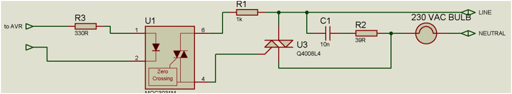
U1 - MOC 3021
U3 - BT136
R1 - 1k
R2 - 39 R
R3 - 330 R
C1 - 10 nF
please don't forget to post your comments.
your hard work seems in your post! nice post.
ReplyDeletethanx bro...
ReplyDeleteGooD WorK,
ReplyDeleteWhat are the other set up are you usung?
means which compiler, debugger?
I Also started learning AVR.
currently observing avr studio 6.
and have purchased arduino board(UNO).
Do you know anything about the method by which we can program AVR controllers through arduino board
seems interesting.. good keep it up.. !
ReplyDelete